To complete the service procedures for the JCB 3CX 4CX backhoe loader excavator, it is necessary to dismantle and assemble the excavator valve control. It is necessary to dismantle and assemble excavator valve control to finish service procedures for JCB 3CX 4CX backhoe loader excavator.So here come the details steps,hope it helps.
Dismantling:
1. Park the machine on firm level ground and apply the parking brake. Lower the loader arms and move the excavator to the right-hand side of the machine, lowering it to the ground. Switch off the engine and remove the starter key. Disconnect the battery.
2. Working in the cab, remove the console panels surrounding the excavator levers as shown in the diagram.
3. Uncouple the rear horn switch electrical connector and remove the wires from the connector. You can use a screwdriver to release the wires/pins from the connector or cut the wires and re-solder them on assembly.
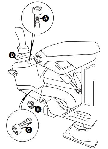
4. Remove the control lever knobs and gaiters.
5. Disconnect the control rods from the excavator valve spools. Remove the bolts securing the complete lever assembly to the excavator valve mounting plate and withdraw the control levers and mounting bracket through the floor aperture.
Assembly:
The assembly process is the reverse of the dismantling sequence.
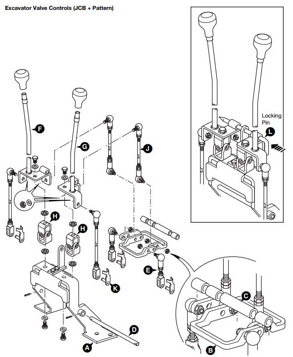
1. Bolt the mounting bracket (A) to the excavator valve mounting plate.
2. Assemble the pivot levers (B) and spacers (C) to the mounting bracket and insert the pivot shaft (D). Fit the short control rods (E) to the pivot lever assembly as shown.
3. Assemble the excavator levers (F) and (G) to the mounting bracket together with the universal joints (H). Fit the longer control rods (J) to the lever assembly as shown. If necessary, loosen the lock nuts and rotate the end fittings to give equal amounts of adjustment (thread) at each end of the control rod.
4. Connect the control rods to the excavator valve spools with the clevis pins (K).
5. Adjust the control rods as necessary (refer to the Adjustment section below). Once adjusted, fit the gaiters over the control levers.
6. Thread the rear horn switch cable through the control lever and fit the wires/pins into the electrical connector. Couple the connector to the chassis harness and fit the control lever knobs.
7. Connect the battery and check that the controls and rear horn switch operate correctly.
8. Refit the console panels around the excavator levers.
Adjustment:
1. Fit the control lever locking pin (L) as shown. If there is no lever locking pin available, use a suitable diameter metal bar.
2. Adjust the control rods until the locking pin is a sliding fit, then tighten the control rods lock nuts. Ensure there is an equal amount of thread at each end of the control rod.
3. Remove the lever locking pin (L).
For more repair cases for JCB Diagnostic Electronic Service Tool, please refer to the JCB Trouble Repair blog articles.
Leave a Reply